Coursework / GE1501 / Pico-0
Pico-0: Getting Started with Raspberry Pi Pico
Exploring how a few lines of MicroPython can control light, read a sensor, and connect code to a physical circuit.
01 / Overview
What is this project?
Pico-0 introduces the Raspberry Pi Pico through four breadboard tasks: blinking an external LED, responding to a light sensor, controlling brightness with pulse-width modulation, and mixing colors with an RGB LED.
The challenges build on each other, moving from digital output to analog sensing and then to continuous brightness control. Thonny provides the programming environment, and MicroPython’s built-in machine module connects the code to the hardware.
02 / Goals
Four circuits. Four challenges.
Blink an external LED
Extend the basic blink circuit to two LEDs that alternate like a police siren.
An LED that responds to light
Use the light sensor to blink an LED in darkness and keep it off in bright light.
Dimming an LED with light
Reverse the starter dimmer so the LED becomes brighter as the room becomes brighter.
Mixing RGB colors
Modify the RGB sequence to display only the rainbow colors: red, orange, yellow, green, blue, indigo, and violet.
03 / How it was made
The breadboard builds
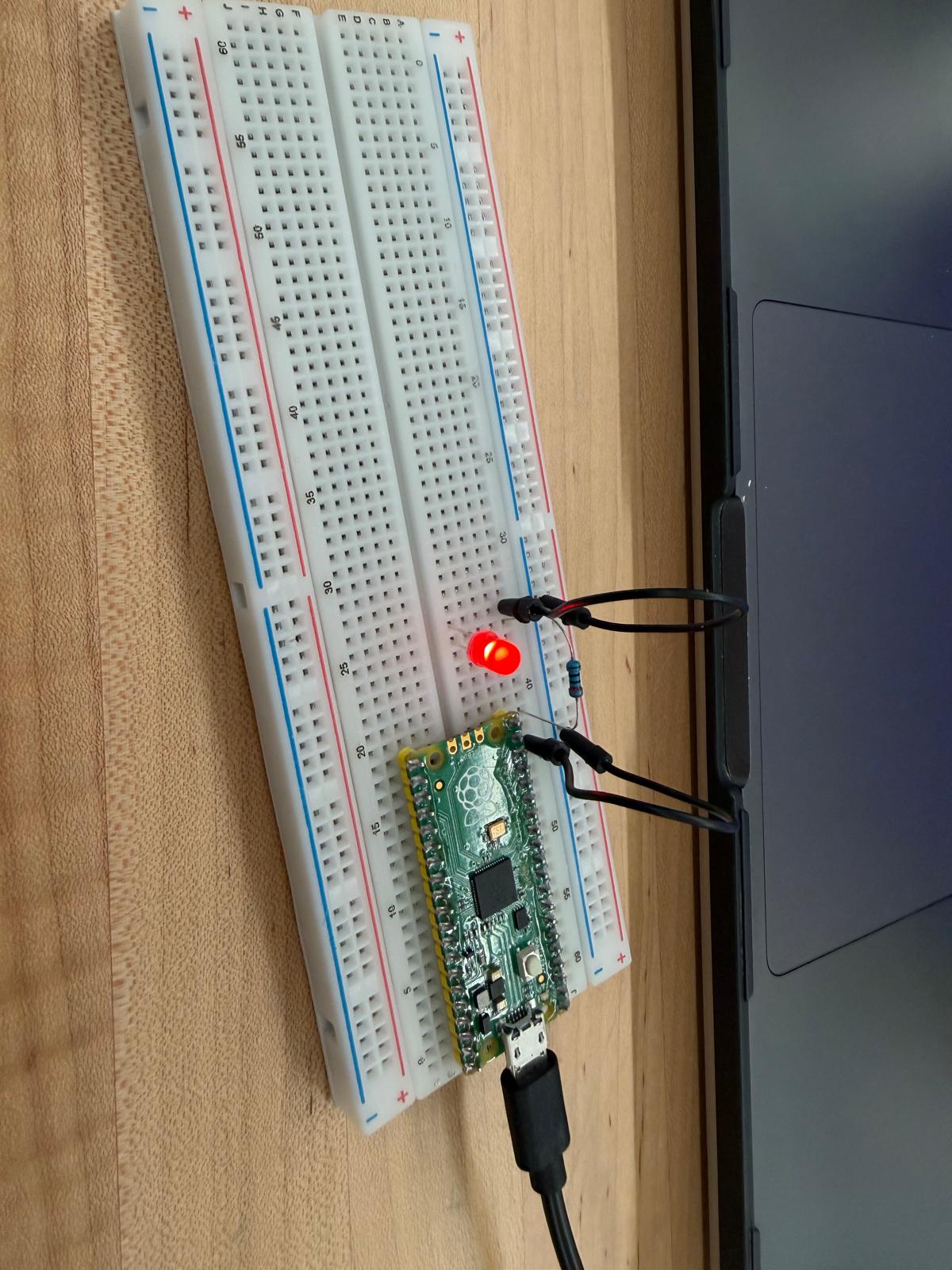
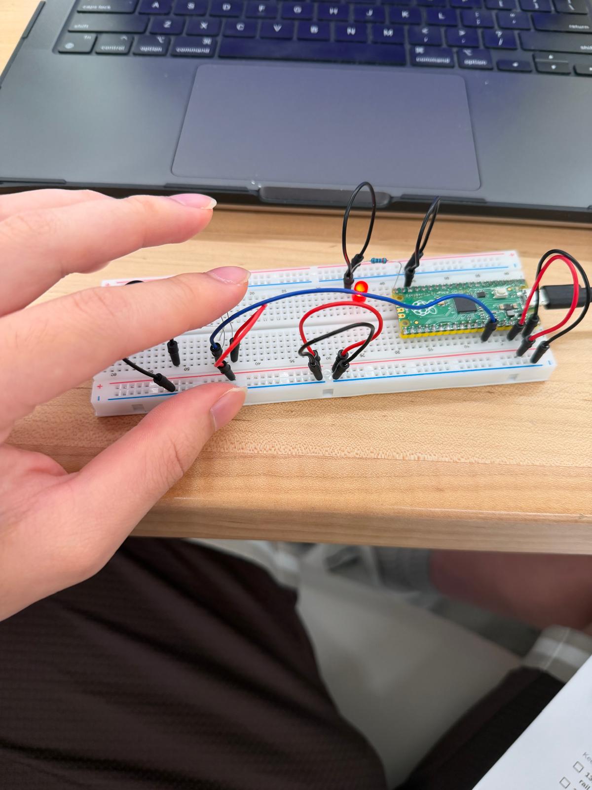
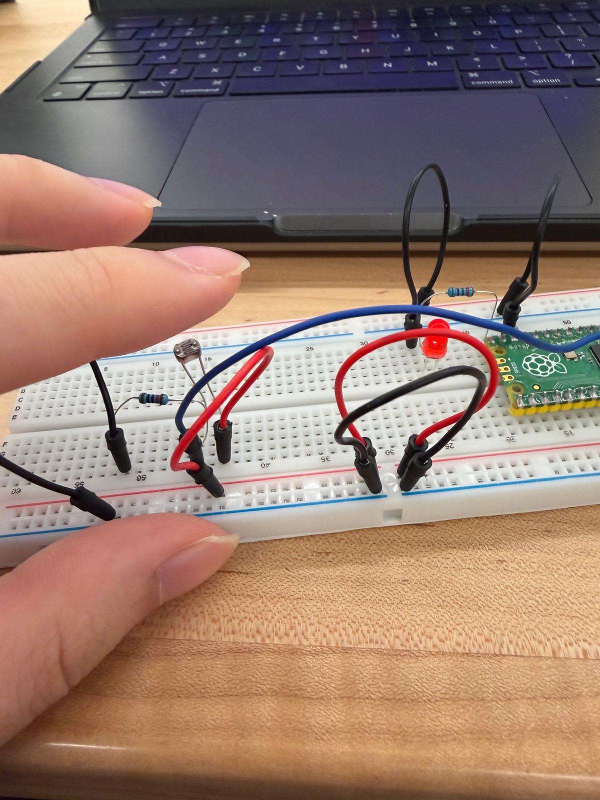
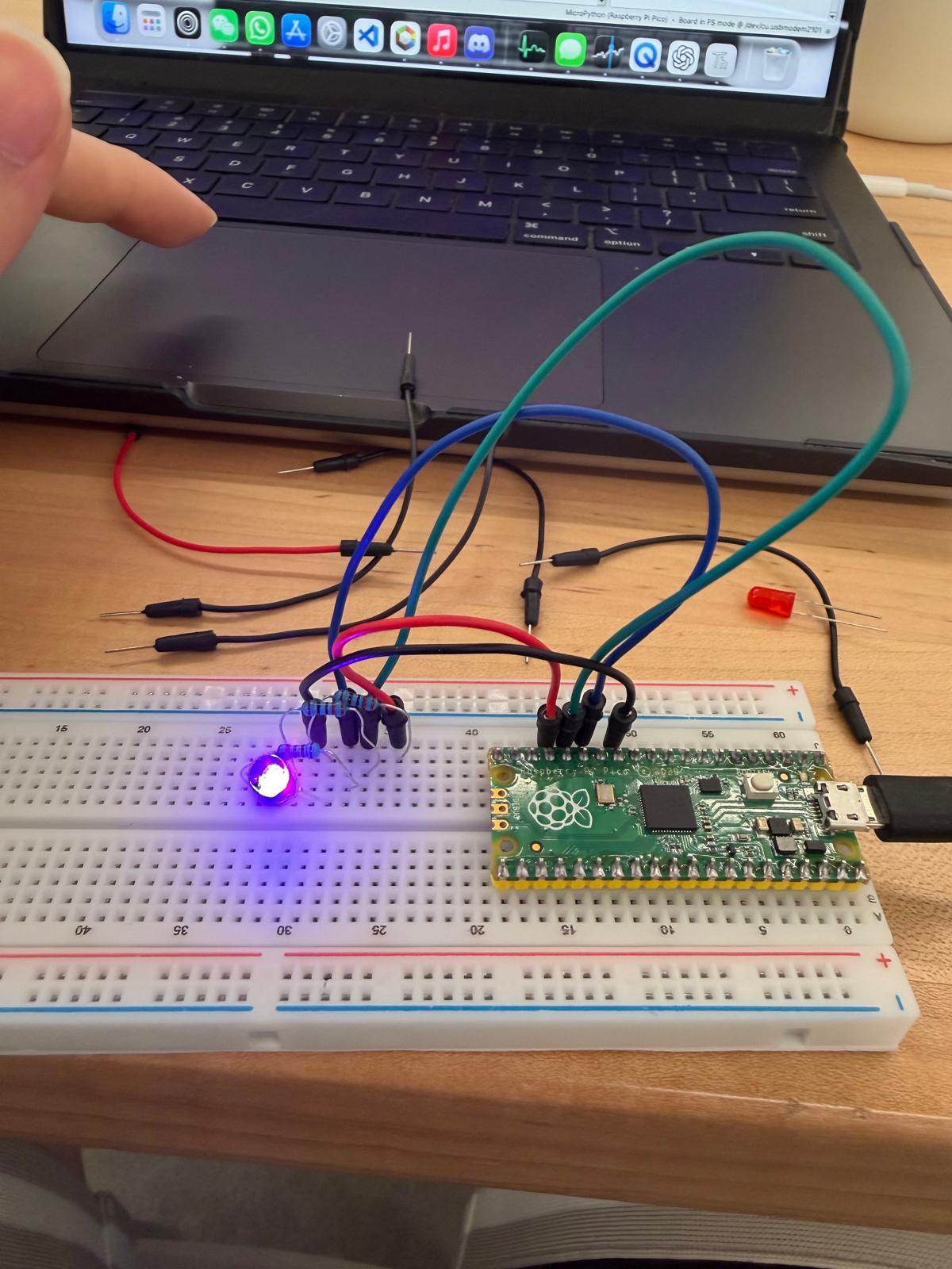
The four task photos document the circuits at the workbench. Open any image to inspect the wiring at full size.
Platform setup
The setup procedure is to connect the Pico in BOOTSEL mode, install the matching MicroPython firmware through Thonny, and select the Pico interpreter. The programs use Pin, ADC, and PWM; no additional Python library is needed.
Disconnect USB power before changing wiring. Keep each LED’s current-limiting resistor in series and use the 3V3(OUT) supply, not the adjacent 3V3_EN pin, for the LDR divider.
Task 01 / Digital output
Blink an external LED
The Pico is connected over USB and mounted on the breadboard. An external red LED, a series resistor, and jumper wires form the first output circuit. The challenge adds a second LED with its own resistor and GPIO connection.
Challenge goal
Extend the basic blink circuit to two LEDs that alternate like a police siren.
Wiring and pin assignments
- GP15 → series resistor → red LED anode; cathode → GND.
Task 02 / Analog input + digital output
An LED that responds to light
A light-dependent resistor (LDR) and a fixed resistor form a voltage divider alongside the LED circuit. A hand over the sensor changes the amount of light reaching it.
Challenge goal
Use the light sensor to blink an LED in darkness and keep it off in bright light.
Wiring and pin assignments
- 3V3(OUT), physical pin 36 → LDR → divider junction.
- Divider junction → GP27 and a 10 kΩ resistor; the resistor’s other end → GND.
- GP15 → series resistor → LED anode; cathode → GND.
Task 03 / Analog input + PWM
Dimming an LED with light
The LED and LDR wiring from Task 2 is reused. The change is in software: the LED output becomes PWM, allowing intermediate brightness levels instead of just on and off.
Challenge goal
Reverse the starter dimmer so the LED becomes brighter as the room becomes brighter.
Wiring and pin assignments
- Reuse the GP27 light-sensor divider from Task 2.
- The corrected copy uses GP15 for the LED, matching Tasks 1 and 2. The uploaded original does not define its LED output pin.
Task 04 / Three PWM outputs
Mixing RGB colors
A common-cathode RGB LED replaces the single-color LED. Its red, green, and blue channels each have a separate series resistor and GPIO connection, while the common cathode connects to ground.
Challenge goal
Modify the RGB sequence to display only the rainbow colors: red, orange, yellow, green, blue, indigo, and violet.
Wiring and pin assignments
- GP13 → series resistor → red channel.
- GP12 → separate series resistor → green channel.
- GP11 → separate series resistor → blue channel; common cathode → GND.
04 / How it works
Reading inputs. Controlling outputs.
These are the four uploaded MicroPython programs, available to read and download unchanged. The explanations describe their logic; the challenge notes identify what still differs from the assignment’s extension goals. Hardware behavior has not been independently verified.
Task 01 / Uploaded source
Blink an external LED
The uploaded program configures GP15 as a digital output. Its loop turns one external LED on for half a second, then off for half a second, repeating continuously.
Expected behavior: One LED blinks with a one-second cycle: 0.5 seconds on and 0.5 seconds off.
Challenge extension: The two-LED challenge requires a second GPIO output and alternating states; the uploaded file controls one LED.
View blink_external_led.py
from machine import Pin
import time

LED_PIN = 15                 # GP number: change to match your wiring
led = Pin(LED_PIN, Pin.OUT)  # set the pin as an output

while True:
    led.value(1)             # LED on
    time.sleep(0.5)          # wait half a second
    led.value(0)             # LED off
    time.sleep(0.5)          # wait half a second
Task 02 / Uploaded source
An LED that responds to light
The program reads the LDR on GP27 and prints the value every 0.2 seconds. When the reading is below the configured DARK threshold of 35,000, it sets the LED on GP15 high. At 35,000 or above, it turns the LED off.
Expected behavior: The LED stays on below the threshold and stays off at or above it.
Challenge extension: The challenge adds a warning blink in darkness. The uploaded file holds the LED steadily on instead.
View ldr_on_off.py
from machine import Pin, ADC
import time

# GP numbers: change to match your wiring
LED_PIN = 15
LDR_PIN = 27                 # must be GP26, GP27, or GP28 (analog pins)

led = Pin(LED_PIN, Pin.OUT)
ldr = ADC(LDR_PIN)

DARK = 35000                 # threshold: set this from your own readings

while True:
    light = ldr.read_u16()   # 0 (dark) to 65535 (bright)
    print(light)
    if light < DARK:         # dark: turn the LED on
        led.value(1)
    else:                    # bright: turn the LED off
        led.value(0)
    time.sleep(0.2)
Task 03 / Uploaded source
Dimming an LED with light
The uploaded file calculates brightness as (50,000 − light) / (50,000 − 35,000), clamps it to 0–1, and scales it to a PWM duty value from 0–65535. This is night-light behavior: less ambient light produces a brighter LED. It specifies 1 kHz PWM and a 0.1-second sampling interval.
Expected behavior: When run on its own in a fresh interpreter, the original file stops with a NameError because LED_PIN is not defined. The corrected copy uses GP15: a reading of 50,000 gives 0% brightness, 42,500 gives 50%, and 35,000 gives 100%.
Challenge extension: The challenge reverses this mapping so brighter ambient light produces a brighter LED. Both the original formula and the corrected copy retain the night-light mapping.
View ldr_dimmer.py
from machine import Pin, PWM, ADC
import time

# GP numbers: change to match your wiring
RED_PIN = 13
GREEN_PIN = 12
BLUE_PIN = 11
LDR_PIN = 27                 # must be GP26, GP27, or GP28 (analog pins)

led = PWM(Pin(LED_PIN))
led.freq(1000)               # 1000 on/off cycles per second
ldr = ADC(LDR_PIN)

# Readings from Task 6: set these from your own room
BRIGHT_ROOM = 50000          # reading in normal room light
DARK_ROOM = 35000            # reading with the LDR covered

while True:
    light = ldr.read_u16()   # 0 (dark) to 65535 (bright)

    # 0.0 in a bright room, 1.0 in a dark room
    level = (BRIGHT_ROOM - light) / (BRIGHT_ROOM - DARK_ROOM)
    level = max(0, min(1, level))     # keep between 0 and 1

    led.duty_u16(int(level * 65535))  # darker room -> brighter LED
    print(light, round(level * 100), "%")
    time.sleep(0.1)
Task 04 / Uploaded source
Mixing RGB colors
Three 1 kHz PWM outputs control red on GP13, green on GP12, and blue on GP11. The set_color function multiplies each 0–255 channel value by 257 to reach the 16-bit duty range. A loop prints and displays each color for one second, then turns all channels off.
Expected behavior: One sequence of red, green, blue, yellow, cyan, magenta, white, purple, and orange, followed by off.
Challenge extension: The challenge requires only rainbow colors in order. The uploaded sequence includes cyan, magenta, and white and is not in rainbow order.
View rgb_led.py
from machine import Pin, PWM
import time

# GP numbers: change to match your wiring
RED_PIN = 13
GREEN_PIN = 12
BLUE_PIN = 11

red = PWM(Pin(RED_PIN))
green = PWM(Pin(GREEN_PIN))
blue = PWM(Pin(BLUE_PIN))

for channel in (red, green, blue):
    channel.freq(1000)       # 1000 on/off cycles per second

def set_color(r, g, b):
    """Set brightness of each color from 0 (off) to 255 (full)."""
    red.duty_u16(r * 257)    # 255 * 257 = 65535 (full brightness)
    green.duty_u16(g * 257)
    blue.duty_u16(b * 257)

colors = [
    ("red",     (255, 0, 0)),
    ("green",   (0, 255, 0)),
    ("blue",    (0, 0, 255)),
    ("yellow",  (255, 255, 0)),
    ("cyan",    (0, 255, 255)),
    ("magenta", (255, 0, 255)),
    ("white",   (255, 255, 255)),
    ("purple",  (128, 0, 128)),
    ("orange",  (255, 128, 0)),
]

for name, (r, g, b) in colors:
    print(name)
    set_color(r, g, b)
    time.sleep(1)

set_color(0, 0, 0)           # turn the LED off
05 / Project gallery
At the workbench